 GitHub
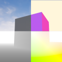
EasySynth
EasySynth is an Unreal Engine plugin for easy creation of image datasets from a moving camera or a multi-camera rig, requiring no C++ or Blueprint knowledge. It leverages native Unreal Engine components to create compelling machine learning datasets, without relying on 3rd party tools.
The plugin works by automatically starting the rendering of a user-defined level sequence, with different camera post-process settings. The outputs are camera poses, including position, rotation, and calibration parameters, together with the following image types:
| Standard color images, as seen while creating the sequence in the editor |  |
| Depth images, representing the depth of a pixel using a grayscale value |  |
| Normal images, representing pixel normals using X, Y, and Z color values |  |
| Optical flow images, representing pixel movement between frames using X, Y, and Z color values |  |
| Semantic images, with every object rendered using the user-defined semantic color |  |
| Model credits: Art Equilibrium |
Installation
The current main branch of this repo is compatible with Unreal Engine 5.2 and 5.3. For source code or binary builds, targeting older engine versions, please consult previous releases.
Major releases also include example projects amongst the release assets.
Install from the marketplace
This is the easiest method if using Windows and you are not interested in modifying the plugin source code.
- Install a compatible Unreal Engine version through the launcher
- Find the EasySynth page inside the
Marketplacetab and hitInstall to Engine - Create a new project and activate the plugin inside the Plugins menu
Install inside a specific project
This method works with both engines installed from the Epic launcher and engines built from source code.
- Create a new Unreal Engine project with the path
<UEProject>- Optional: Use some of the provided Unreal Engine templates that come with a prebuilt level layout
- Exit the editor
- Create and navigate to the
<UEProject>/Pluginsdirectory - Clone this repo, or unzip the appropriate release inside the
<UEProject>/Pluginsdirectory - Reopen your project
Install inside the engine using prebuilt binaries
This method works with both engines installed from the Epic launcher and engines built from source code but requires using appropriate binaries.
- Navigate to the
<UEPath>/Engine/Pluginsdirectory - Unzip the appropriate release
- Restart the engine
- Create a new project and activate the plugin inside the Plugins menu
Install inside the engine by building from source code
This method only works with engines built from source code.
- Navigate to the
<UEPath>/Engine/Pluginsdirectory - Clone this repo
- Navigate to the
<UEPath>directory - Run the
makecommand - Restart the engine
- Create a new project and activate the plugin inside the Plugins menu
How to use
Check out our demonstration video showcasing everything from setting up the project to rendering output images.
Setup
- Create a project as described in the
Installationsection - Create a level layout yourself, or look online for available levels that suit your needs
- Click the EasySynth button in the toolbar to open the EasySynth widget
Semantic annotation
You can skip this step if you don't need semantic rendering.
The first step is to define the needed semantic classes, which you can modify at any point. To open the semantic classes editor, click the Manage Semantic Classes button. All modifications execute immediately. To close the editor, click the Done button.
This editor allows you to:
- Add a new semantic class
- Remove an existing semantic class
- Modify an existing semantic class name
- Modify an existing semantic class color
Next, you should assign semantic classes to all of the level actors. To do this:
- Select one or more actors of the same class in the editor window or by using the World Outliner
- Supported mesh types are static mesh, skeletal mesh and landscapes
- Assign them a class by clicking on the
Pick a semantic classbutton and picking the class
To toggle between original and semantic color, use the Pick a mesh texture style button. Make sure that you never save your project while the semantic view mode is selected.
A CSV file including semantic class names and colors will be exported together with rendered semantic images. This file can be used for later reference or can be imported into another EasySynth project.
Sequence rendering
Image rendering relies on a user-defined Level Sequence, which represents a movie cut scene inside Unreal Engine.
IMPORTANT: Camera(s) used with the sequencer have to be manually added to the level and then linked with the sequencer. Adding a camera through the sequencer itself will cause unexpected behavior or crashes, due to issues caused by spawnable/possessable sequence actors. For more information see:
https://docs.unrealengine.com/4.27/en-US/AnimatingObjects/Sequencer/Overview/SpawnablesPossessables/
You only need the LevelSequence asset for rendering. Skip anything that has to do with the LevelSequenceActor. Here are some materials on how to get started:
- https://docs.unrealengine.com/4.27/en-US/AnimatingObjects/Sequencer/Overview/
- https://youtu.be/-NmHXAFX-3M
The following tutorial is a good starting point for working with skeletal meshes inside the sequencer:
Setting up rendering options inside the EasySynth widget:
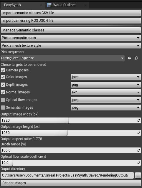
- Optionally import semantic classes from a CSV file (or create them manually)
- Optionally import camera rig from a ROS format JSON file (or create it manually)
- Pick the created level sequence
- Choose the desired rendering targets using checkboxes
- Choose the output image format for each target
- jpeg - 8-bit image output intended for visual inspection due to lossy jpeg compression,
- png - 8-bit image output with lossless png compression
- exr - 16-bit image output with lossless exr compression, to open them with OpenCV in Python use
cv2.imread(img_path, cv2.IMREAD_ANYCOLOR | cv2.IMREAD_ANYDEPTH)
- Choose the output images width and height
- The aspect ratio of the camera will be updated according to the chosen output size
- Choose the depth infinity threshold for depth rendering
- Choose the appropriate scaling coefficient for increasing optical flow image color saturation
- Choose the output directory
Start the rendering by clicking the Render Images button.
IMPORTANT: Take recorder, unfortunately, cannot be used to record sequences, as we could not find a way to integrate sequences it produces with our plugin. If you have an idea how this can be done feel free to leave your suggestions in the issues.
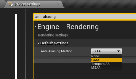
IMPORTANT: If you need anti-aliasing applied on output images, set Anti-Aliasing Method in project settings to FXAA. Other options will have no effect and output images will have jagged edges.
IMPORTANT: Do not close a window that opens during rendering. Closing the window will result in the successful rendering being falsely reported, as it is not possible to know if the window has been closed from the plugin side.
Multi-camera rigs
EasySynth seamlessly supports rendering using rigs that contain multiple cameras. To create a rig, add an empty actor to the level, and then add any number of individual camera components to the actor, position them as desired relative to the actor position. Then, add the actor to the level sequence and assign it to the camera cut track. When you start rendering, outputs from all of the rig cameras will be created in succession.
Camera rig information can be imported and exported using ROS format JSON files with a specific structure. Clicking on the button Import camera rig ROS JSON file and choosing a valid file will create an actor that represents the described rig inside the level. The camera rig file is also exported during rendering to the selected output directory. Its structure will be described below.
Workflow tips
- You can use affordable asset marketplaces such as Unreal Engine Marketplace or CGTrader to obtain template levels. Ones that provide assets in the Unreal Engine
.uassetformat are preferred. Formats such asFBXorOBJcan lose their textures when imported into the UE editor. - When semantic labeling levels with many assets, utilize the World Outliner as much as possible. Use the search option to filter similar actors and bulk-select them so that all of them are labeled in one click.
- If you want images to be spaced out more inside the level sequence (instead of being very close in order to provide a smooth video), you can set the custom level sequence FPS to a small value (1 FPS or lower) inside the Sequencer editor.
- To avoid adding keyframes manually, select the
 button inside the sequence editor toolbar. After you create the first keyframe, this will automatically add one at the current time for any moved asset.
 - To avoid potential artifacts, make sure the camera trajectory line is always smooth and does not contain "edged" turns - except when that is done intentionally.
- To avoid slow camera acceleration at the sequence start, create an additional keyframe for the camera actor
Locationbefore the 0th frame in the timeline and place the actor a little bit behind its place at the beginning of the sequence. These negative time frames will not be rendered, but the camera actor will have initial speed in the first rendered frame instead of starting from a standstill. - Although changing the
CameraComponenetoffset/translation in relation to theCameraActoris possible, the exported camera poses will beCameraActorposes. If the relative translation is not zero, exported poses will not match locations where the actual image is taken from and you will have to compensate for that manually.
Outputs' structure details
Depth images
Depth image pixel values represent the proportional distance between the camera plane and scene objects.
- A camera plane is a plane that contains the camera position and is normal to the camera direction vector.
- Depth is equal to the length of a normal from a scene object on the camera plane. This means we use linear depth, in contrast to the radial depth which would imply that the depth is equal to the distance between the object and the camera position.
- Depth values are scaled between 0 and the specified
Depth rangevalue.
Camera pose output
If requested, the plugin exports camera poses to the same output directory as rendered images.
Output is the CameraPoses.csv file, in which the first line contains column names and the rest contain camera poses for each frame. Columns are the following:
| Column | Type | Name | Description |
|---|---|---|---|
| 1 | int | id | 0-indexed frame id |
| 2 | float | tx | X position in centimeters |
| 3 | float | ty | Y position in centimeters |
| 4 | float | tz | Z position in centimeters |
| 5 | float | qx | Rotation quaternion X |
| 6 | float | qy | Rotation quaternion Y |
| 7 | float | qz | Rotation quaternion Z |
| 8 | float | qw | Rotation quaternion W |
| 9 | float | t | Timestamp in seconds |
The coordinate system for saving camera positions and rotation quaternions is the same one used by Unreal Engine, a left-handed Z-up coordinate system.
Coordinates will likely require conversion to more common reference frames for typical computer vision applications. For more information, we recommend this Reddit post. Still, it seems to be the cleanest option, as exported values will match the numbers displayed inside the engine.
Following is an example Python code for accessing camera poses:
import numpy as np
import pandas as pd
from scipy.spatial.transform import Rotation as R

poses_df = pd.read_csv('<rendering_output_path>/<camera_name>/CameraPoses.csv')

for i, pose in poses_df.iterrows():

    # Rotation quaternion to numpy array
    quat = pose[['qx', 'qy', 'qz', 'qw']].to_numpy()

    # Quaternion to rotation object
    rotation = R.from_quat(quat)

    # Rotation to Euler angles
    euler = rotation.as_euler('xyz')

    # Rotation to 3x3 rotation matrix, than to 4x4 rotation matrix
    mat3 = rotation.as_matrix()
    mat4 = np.hstack((mat3, np.zeros((3, 1))))
    mat4 = np.vstack((mat4, np.array([0.0, 0.0, 0.0, 1.0])))

    # Adding translation to the 4x4 transformation matrix
    mat4[:3, 3] = pose[['tx', 'ty', 'tz']].to_numpy()

    # Convert camera pose to a camera view matrix
    view_mat = np.linalg.inv(mat4)
Camera rig ROS JSON file
Camera rig JSON files contain spatial data that includes 4 fields for each rig camera:
intrinsics- Camera intrinsics matrixrotation- Rotation quaternion relative to the rig origintranslation- Translation vector relative to the rig originsensor_size- Sensor width and height in pixels, used to calculate camera FOV
Rotation and translation values follow the UE coordinate system convention and are relative to the rig origin.
Camera sensor sizes and aspect ratios will not be updated at this point, but they will be calculated according to the requested output image size when the rendering starts.
Following is a ROS JSON file example for a rig with two parallel cameras with the FOV of 90 degrees, facing forward. The difference can be found in the sign of the translation vector Y-axis.
{
	"cameras":
	{
		"c0":
		{
			"intrinsics": [ 960, 0, 960, 0, 960, 540, 0, 0, 0 ],
			"rotation": [ 0, 0, 0, 1 ],
			"translation": [ 0, -30, 0 ],
			"sensor_size": [ 1920, 1080 ]
		},
		"c1":
		{
			"intrinsics": [ 960, 0, 960, 0, 960, 540, 0, 0, 0 ],
			"rotation": [ 0, 0, 0, 1 ],
			"translation": [ 0, 30, 0 ],
			"sensor_size": [ 1920, 1080 ]
		}
	}
}
Normal images
Normal images contain color-coded vector values that represent surface normals for each pixel, relative to the camera view vector.
Vector axis values that range from -1.0 to 1.0, are mapped to RGB color channels using the formula (xyz + 1.0) / 2.0.
The axis mappings are as follows:
- R: [0 - 1] => (towards left - towards right)
- G: [0 - 1] => (towards bottom - towards top)
- B: [0 - 1] => (towards camera - away from camera)
IMPORTANT: Normal vectors are not guaranteed to be normalized.
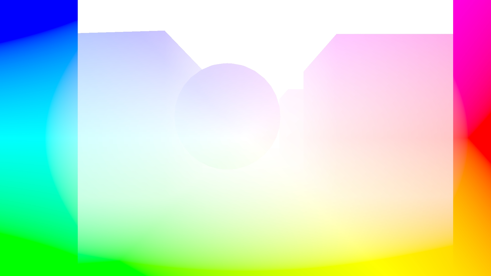
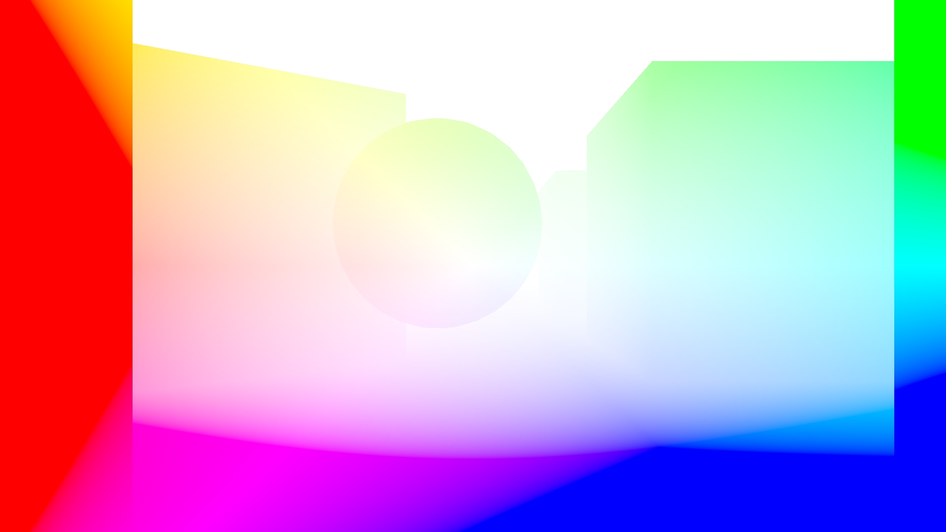
Optical flow images
Optical flow images contain color-coded optical flow vectors for each pixel. An optical flow vector describes how the content of a pixel has moved between frames. Specifically, the vector spans from coordinates where the pixel content was in the previous frame to where the content is in the current frame. The coordinate system the vectors are represented in is the image pixel coordinates, with the image scaled to a 1.0 x 1.0 square.
Optical flow vectors are color-coded by picking a color from the HSV color wheel with the color angle matching the vector angle and the color saturation matching the vector intensity. If the scene in your sequence moves slowly, these vectors can be very short, and the colors can be hard to see when previewed. If this is the case, use the optical flow scale parameter to proportionally increase the image saturation.
The following images represent optical flows when moving forward and backward respectively. Notice that all of the colors are opposite, as in the first case pixels are moving away from the image center, while in the second case pixels are moving toward the image center. In both examples, the fastest moving pixels are the ones on the image edges.
Our implementation was inspired by the ProfFan's UnrealOpticalFlowDemo, but we had to omit the engine patching to make this plugin as easy to use as possible (i.e. not requiring the engine to be manually built). The shader code that renders optical flow is baked inside the optical flow post-process material. It can be accessed by opening the post-process material from the plugin's content inside the Unreal Engine editor.
IMPORTANT: Due to Unreal Engine limitations optical flow rendering assumes all objects other than the camera are stationary. If there are moving objects in the scene while rendering the sequence, the optical flow for these pixels will be incorrect.
Following is an example Python code for loading optical flow from an .exr image and applying it to the appropriate image from a sequence, to produce its successor:
import cv2
import numpy as np

# Load the base image
base_image = cv2.imread('<rendering_output_path>/ColorImage/<sequence>.0010.jpeg')
h, w, _ = base_image.shape

# Load the optical flow image from an .exr file
optical_flow_image = cv2.imread(
  '<rendering_output_path>/OpticalFlowImage/<sequence>.0011.exr',
  cv2.IMREAD_ANYCOLOR | cv2.IMREAD_ANYDEPTH)

# Convert the image to HSV, where H is the angle and S is the intensity on the color wheel
optical_flow_image = cv2.cvtColor(optical_flow_image, cv2.COLOR_BGR2HSV)
angle, magnitude = optical_flow_image[:, :, 0], optical_flow_image[:, :, 1]

# Convert the shift from polar to cartesian coordinates (magnitude, angle => x, y)
# Multiply the result by -1 since we need the position of an output pixel on the previous image
x_flow, y_flow = cv2.polarToCart(magnitude, angle, angleInDegrees=True)
x_flow = np.round(-w * x_flow).astype(np.int32)
y_flow = np.round(-h * y_flow).astype(np.int32)

# Update each pixel value with the value of the shifted pixel
mapped_image = np.zeros((h, w, 3), dtype=np.uint8)
for i in range(h):
    for j in range(w):
        # Make sure the shifted pixel is inside the base image
        y = i + y_flow[i, j]
        x = j + x_flow[i, j]
        if 0 <= x < w and 0 <= y < h:
            mapped_image[i, j, :] = base_image[y, x]

# Store the output image
cv2.imwrite('mapped_image.jpeg', mapped_image)
Advanced version of this code, utilizing torch and CUDA, can be found in Scripts/optical_flow_mapping.py.
Contributions
This tool was designed to be as general as possible, but also to suit our internal needs. You may find unusual or suboptimal implementations of different plugin functionalities. We encourage you to report those to us, or even contribute your fixes or optimizations. This also applies to the plugin widget Slate UI whose current design is at the minimum acceptable quality. Also, if you try to build it on Mac, let us know how it went.
Unreal Engine is a registered trademark of Epic Games, Inc.